15 Results
View results:
Sort by:

The events of recent years remind us of the importance of earthquake engineering in seismic regions. For you as an engineer, the design of structures in earthquake-prone areas is a constant trade-off between economic efficiency – the financial possibilities – and structural safety. If a collapse is inevitable, engineers must estimate how it will affect the structure. This article aims to provide you with an option on how to perform this estimation.
This article will introduce to you the “Surface Results Adjustments” in RFEM 6, corresponding to the "Average Region" function implemented in RFEM 5.
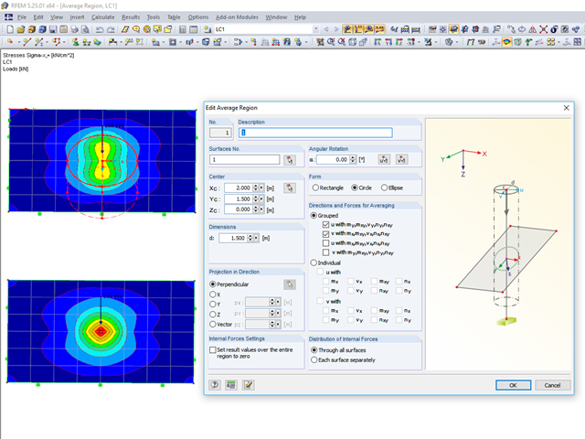
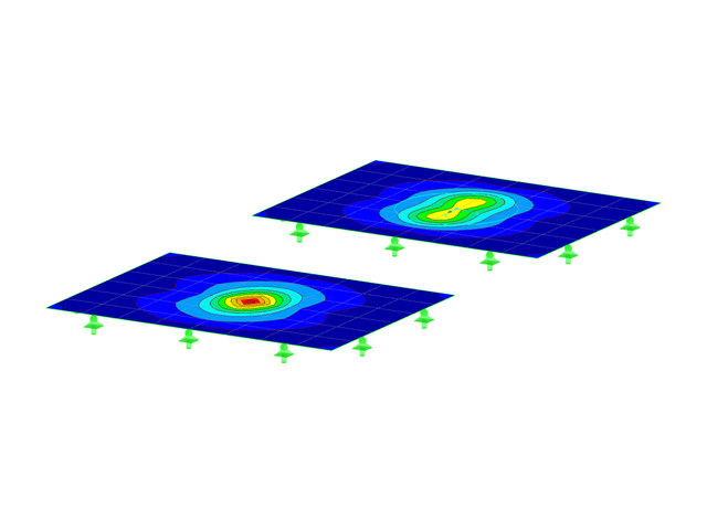
RFEM 5 provides the option to define a smoothing area in the "Results" → "New Average Region" menu. You can choose a rectangular, circular, or elliptical shape. With this tool you can, for example, "smooth" singularities due to nodal loads in a desired averaged region.
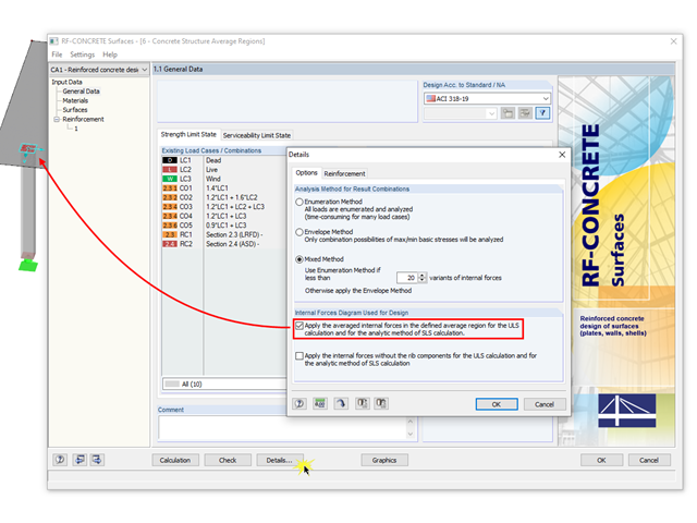
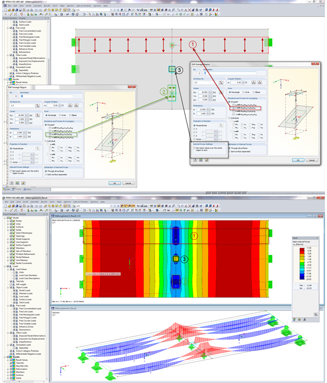
The averaged internal forces from the previously defined average regions can also be used for designing concrete surfaces. To do this, click [Details] in RF‑CONCRETE Surfaces, then select the corresponding check box. This function is accessible only if you previously defined an average region.

RF‑CONCRETE Surfaces for RFEM 5 allows you to use averaged internal forces for design of concrete surfaces.

According to Clause 3.2.2, EN 1993-1-3 allows the use of an average increased yield strength fya of a cross-section due to strain hardening.

Reinforced concrete surface design for slabs, plates, and walls is possible in the RF-CONCRETE Surfaces module according to the ACI 318-19 or the CSA A23.3-19 standard. A common approach for slab design is the use of design strips for determining the average one-way internal forces over the width of the strip. This design strip method essentially takes a two-way slab element and applies a simpler one-way approach to determine the required reinforcement needed along the strip length.
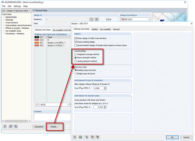
If an aluminum member section is comprised of slender elements, failure can occur due to the local buckling of the flanges or webs before the member can reach full strength. In the add-on module RF-/ALUMINUM ADM, there are now three options for determining the nominal flexural strength for the limit state of local buckling, Mnlb, from Section F.3 in the 2015 Aluminum Design Manual. The three options include sections F.3.1 Weighted Average Method, F.3.2 Direct Strength Method, and F.3.3 Limiting Element Method.

Wind is the only climatic load acting on every type of structure in every country in the world, unlike snow. The wind speed depends on the geographic location of the building. Currently, this is one of the main reasons for the necessity of regional division (wind zone) and consideration of the altitude stipulated within the official standards; the variation of the dynamic pressures according to the height above the ground for a "normal" site deprived of masking effect should be taken into account as well.
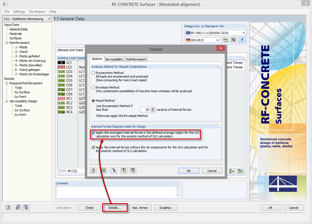
In order to use internal forces from average regions also for the design of concrete surfaces, you have to activate them in the module. For this, click the [Details] button in the "Tools" tab and select the option "Apply the averaged internal forces in the defined average region for the ULS calculation and for the analytic method of SLS calculation."
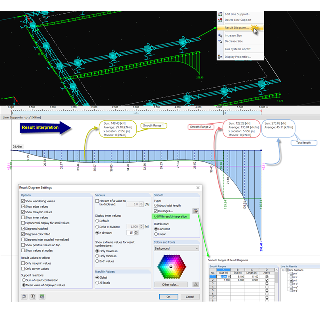
When evaluating results in the smooth state, you can display the average and sum values. This option is also available for parts of a line, a section, and so on. By importing the graphic into the printout report, you can document these values in the structural analysis.
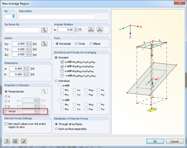
For average regions, you can use a vector as a projection. Thus, it is possible to define average regions for curved surfaces as well.
![Reduction of Building to Cantilever Structure: The individual mass points represent the floors. The deflection due to the normal compression forces shown in (a) is (b) converted into equivalent moments of displacement or shear forces [2].](/en/webimage/009762/2420261/01-en-png-12-png.png?mw=640&hash=2753cb61c54a78756b34fd3ab03c92ed01b9fd39)
For the ultimate limit state design, EN 1998 1, Sections 2.2.2 and 4.4.2.2 [1], requires the calculation considering the second-order theory (P-Δ effect). This effect may be neglected only if the interstory drift sensitivity coefficient θ is less than 0.1. The coefficient θ is defined as follows:
$$\mathrm\theta\;=\;\frac{\displaystyle{\mathrm P}_\mathrm{tot}\;\cdot\;{\mathrm d}_\mathrm r }{{\mathrm V}_\mathrm{tot}\;\cdot\;\mathrm h}\;(1)$$
where
θ is the interstory drift sensitivity coefficient,
Ptot is the total gravity load at and above the story considered in the seismic design situation (see Expression 2),
dr is the design interstory drift, evaluated as the difference of the average lateral displacements dS at the top and bottom of the story under consideration; for this, the displacement is determined using the linear design response spectrum with q = 1.0,
Vtot is the total seismic story shear determined using the linear design response spectrum,
h is the interstory height.
In RFEM, areas can be defined where the internal forces in surfaces are not displayed with the real distribution from FE calculation, but as mean values. You can use various settings for averaging the internal forces. There are three possible application areas of the "Average Region" function.
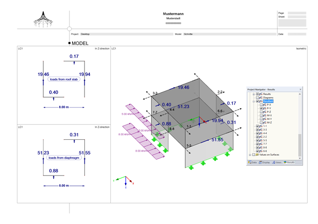
To obtain forces for designing surface connections, you can look at the results using the "Result diagram" function of a connection line. Among other things, there are auxiliary tools such as "Average line" and "Average region".